What is LDR?
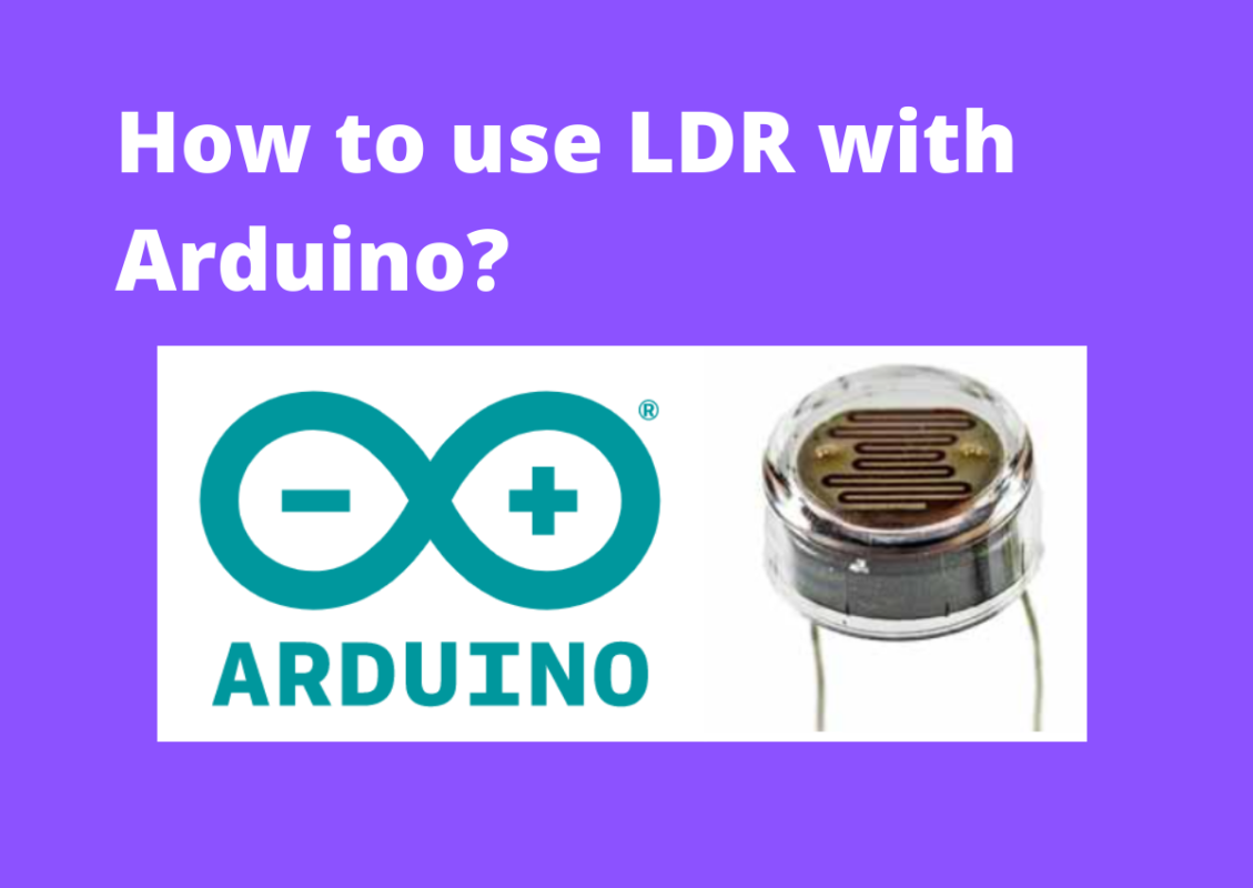
LDR is a small electronic component used in electronic circuits for different purposes. LDR full form is Light Dependent Resistor which is also known as a photoresistor or even photocell.
LDR is very different from the other types of resistors used in the electronic circuit building processes like the carbon film resistor, metal oxide film resistor. It is specifically designed for the light sensitivity and the changes of resistance it experiences depending on the appearance of lights. Light Dependent Resistor provides a large change in resistance for changes in the light level.

Because of its light sensitivity, when light falls upon it, then the resistance also changes. When the light level increases the level of resistance decreases and the resistance increases when the light level decreases. The sensitivity of LDR varies with the wavelength of the incident light.
Photoresistors or LDRs are made from semiconductor materials to ensure their light-sensitive properties. The popular material for this photoresistor is cadmium sulfide, CdS, although the use of these cells is now restricted in Europe for environmental issues with the cadmium.
LDR symbol/photoresistor symbol:
The LDR symbol that is used in the electronic circuit is shown using the arrows shining on it, where arrows are used to show the light falling on it. There are two types of symbols used for LDR, with a rectangular box and the zig-zag line resistor circuit symbol.

How an LDR works?
Remember that electrical current comprises the movement of electrons within a material. Normally, a good conductor includes a large number of free electrons in it and when there is a potential difference, the free electrons can drift in the given direction. On the other hand, high resistance insulators have very few electrons on them and it is very hard to make them move and therefore a current to flow.
An LDR is made of semiconductor materials with high resistance. As the LDR poses the high resistance and hence very few electrons that are free and able to move- the majority of electrons are locked into the crystal lattice and they are not able to move. Therefore, in such a state, the LDR occupies a high resistance.
When the light falls on the semiconductor, the light photons are absorbed by the semiconductor lattice and some of their energy is moved to the electrons.
How to connect LDR with Arduino?
To connect Light Dependent Resistance with Arduino, you need the following components:
- Arduino Board
- LDR
- 7k resistor
- Connecting wire
Step 1: The analog pin 0 of the Arduino board will be connected to the one terminal of the LDR sensor and the other terminal will be connected to the 5V output pin of the Arduino board.
Step 2: The GND pin of Arduino will be connected through a 4.7k resistor and intersect the analog 0 pin of the Arduino.

I am going to show you how to connect LDR with Arduino and modify the fixed delay time of Blink Sketch using the LDR sensor. In the Blink Sketch, we use the delay() function parameter in milliseconds but here I will change this parameter to the LDR sensor’s input value as the dealy() functions input.
This is an interesting Arduino hack that will help you understand customizing Arduino code based on your need and how to take sensor value as an input parameter to control LED with LDR.
Hence, the following sketch reads the light level of the LDR connected to analog pin 0 and the level striking the LDR will change the blink rate of the LED connected to digital pin 13.
Arduino code for controlling LED with LDR sensor
const int ledPin = 13; // LED connected to digital pin 13
const int sensorPin = 0; // connect sensor to analog input 0
void setup()
{
pinMode(ledPin, OUTPUT); // enable output on the led pin
}
void loop()
{
int rate = analogRead(sensorPin); // read the analog input
digitalWrite(ledPin, HIGH); // set the LED on
delay(rate); // wait duration dependent on light level
digitalWrite(ledPin, LOW); // set the LED off
delay(rate);
}
Note that the 4.7k resistor that I am using in this circuit is not mandatory to use. You can use any resistor from 1K to 10K value for your project.
int rate = analogRead(sensorPin); // read the analog input
The above statement of code is used to read the LDR sensor value and store it to the rate variable. The change in light level on the LDR will change the voltage level on the analog pin 0.
You may have a question about the analogRead() function value in this code. What is the value that will be given by the anlogRead() function?
Normally, the LDR provides a value that ranges from around 200 when it is dark to 800 or more when it is very dark. I am going to use this value to determine the duration of the delay time for LED. How long the LED will be in the off state and on the state depends on the light intensity. The blinking time for LED will increase in case of high intensity.
Using map() function in Arduino with LDR
While using the LDR value as a delay timer for Blink Sketch, you can balance the blink rate by using the Arduino map() function. You can take the value of the LDR sensor stored in the rate variable as a parameter in the map() function.
Here is the code:
const int ledPin = 13;
// declaring the integer variable to connect LED to digital pin 13
const int sensorPin = 0;
// sensorPin variable for connecting to analog pin 0
Now, create two variable minDuration and maxDuration to define minimum and maximum delay between blinks.
Const int minDuration=100;
// set minimum duration of delay (minimum wait between blinks) to 100 milliseconds
Const int maxDuration = 1000;
// set minimum duration of delay (maximum wait between blinks) to 1000 milliseconds
void setup()
{
pinMode(ledPin, OUTPUT); // enable output on the led pin
}
void loop()
{
int rate = analogRead(sensorPin);
// read the analog input, LDR sensor value and store it to rate variable
rate = map(rate, 200,800,minDuration, maxDuration); // convert to blink rate
// map function will scale the minimum and maximum duration between blinks and storing it to the variable
rate = constrain(rate, minDuration,maxDuration); // constrain the value
digitalWrite(ledPin, HIGH);
// set the LED on
delay(rate);
// wait duration dependent on light level
digitalWrite(ledPin, LOW);
// set the LED off
delay(rate);
}
Run this code and check how the wait time between blinks is getting changed depending on the amount of light that falls on the LDR sensor.
Here is a question,
How to check the real-time value of the rate variable?
Yes, you can check the value of the rate variable on your computer through Serial Monitor. Below is the revised code for you to print the value on your Serial Monitor. You open the Serial Monitor window in the Arduino IDE by clicking on the icon on the right of the top bar.
const int ledPin = 13; // LED connected to digital pin 13
const int sensorPin = 0; // connect sensor to analog input 0
// the next two lines set the min and max delay between blinks
const int minDuration = 100; // minimum wait between blinks
const int maxDuration = 1000; // maximum wait between blinks
void setup()
{
pinMode(ledPin, OUTPUT); // enable output on the led pin
Serial.begin(9600); // initialize Serial
}
void loop()
{
int rate = analogRead(sensorPin); // read the analog input
// the next line scales the blink rate between the min and max values
rate = map(rate, 200,800,minDuration, maxDuration); // convert to blink rate
rate = constrain(rate, minDuration,maxDuration); // constrain the value
Serial.println(rate); // print rate to serial monitor
digitalWrite(ledPin, HIGH); // set the LED on
delay(rate); // wait duration dependent on light level
digitalWrite(ledPin, LOW); // set the LED off
delay(rate);
}


